Research
CNN-Based Camera Pose Estimation and Localisation of Scan Images for Aircraft Visual Inspection
Overview Research area: Robotics and computer vision — specifically deep-learning-based monocular camera pose estimation, applied to automated aircraft exterior inspection. Technical level: Advanced.
- arXiv
- 2511.18702
- Published
- 2025-11-24
- Authors
- Xueyan Oh, Leonard Loh, Shaohui Foong, Zhong Bao Andy Koh, Kow Leong Ng, Poh Kang Tan, Pei Lin Pearlin Toh, U-Xuan Tan
AI summary
Overview
Research area: Robotics and computer vision — specifically deep-learning-based monocular camera pose estimation, applied to automated aircraft exterior inspection.
Technical level: Advanced. The paper assumes familiarity with convolutional neural networks, camera pose regression, loss-function design, quaternion orientation representations, and camera calibration concepts such as field of view and pan-tilt-zoom control.
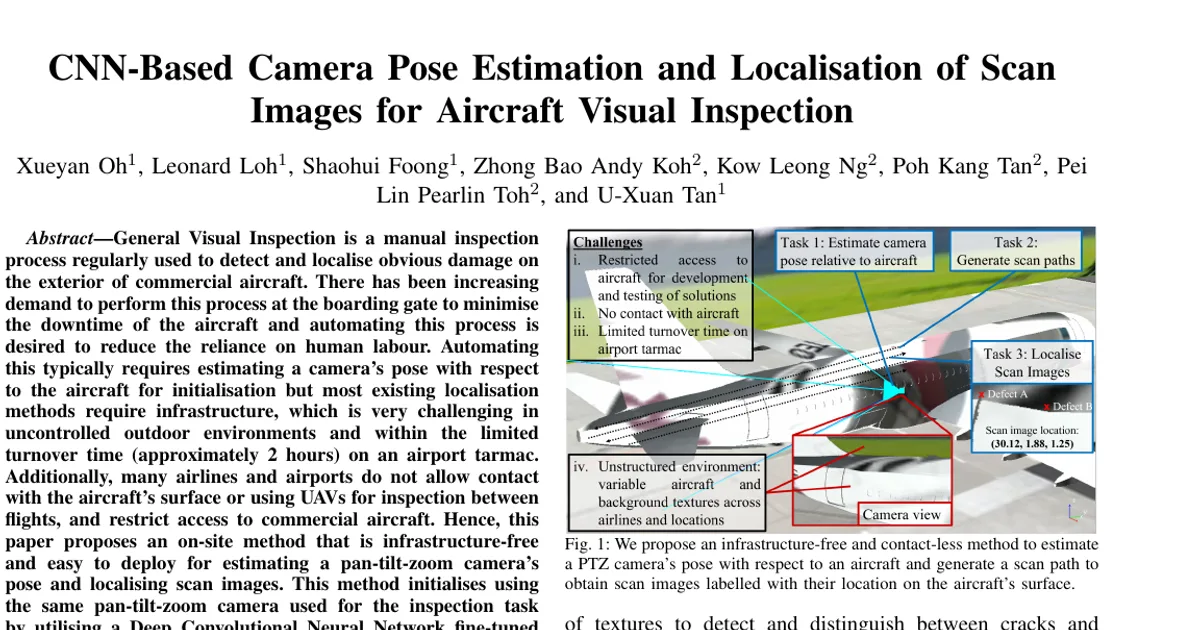
Scope in one sentence: The paper presents an infrastructure-free workflow that uses a Pan-Tilt-Zoom (PTZ) camera and a CNN fine-tuned only on synthetic images to estimate the camera's pose relative to an Airbus A320 and then label scan images with their location on the aircraft's surface.
What This Paper Is About
General Visual Inspection (GVI) of commercial aircraft exteriors is currently performed by hand by trained personnel, and automating it would reduce labour and error rates. Automation requires knowing where the inspection camera is relative to the aircraft, but on an airport tarmac there is roughly a 2-hour turnover window, no infrastructure, no permission to touch the aircraft's surface, and no permission to fly UAVs.
The goal is an easily deployable, contact-less, infrastructure-free method that estimates a PTZ camera's pose from a single real image using a network fine-tuned only on synthetic images, and then plans a scan path that captures images labelled with the 3D coordinates of their centre pixels.
Key Contributions
- An end-to-end workflow for producing scan images labelled with their location on an aircraft's surface, using a PTZ camera mounted on an extendable mast, split into a Preparation Phase and a repeatable Deployment Phase.
- A method for initialising and estimating the inspection camera's pose without physical contact with, or prior access to, a real aircraft — a DCNN fine-tuned on only synthetic images of a 3D aircraft model.
- A new loss component, the Image Centre Scene Coordinate (ICSC) loss, that exploits the known geometry of the aircraft (modelled as a cylinder) to relate the predicted camera position and orientation to the scene point under the image's centre pixel; the resulting network is called ICSC-PoseNet.
- A scan path generation and image localisation method that converts an interpolated 3D aircraft point cloud into PTZ pan-tilt values and selects scan points using the camera's field of view and a desired overlap factor.
The paper states it builds on a preliminary version published at ICRA 2021, with the differences being: the end-to-end workflow, experimental validation with aircraft in different scenes, a scanning strategy for labelling images of the upper-half surface, and a demonstration of the complete workflow on a real aircraft.
Main Findings
- Pose estimation accuracy on real aircraft: The authors report root-mean-square camera pose estimation errors of less than 0.24 m and 2° for all real scenes.
- Synthetic-data training works: ICSC-PoseNet achieved the lowest error when tested on all synthetic and real scenes except Real Scene 3, where the difference in position error is described as marginal.
- Synthetic test sets: On Syn60 (300 test images, 60° HFOV), ICSC-PoseNet reached median 0.063 m, 0.50° and RMSE 0.085 m, 0.63°, versus PoseNet+ at median 0.067 m, 0.60° and RMSE 0.10 m, 0.75°. On Syn725 (300 test images, 72.5° HFOV), ICSC-PoseNet reached median 0.050 m, 0.36° and RMSE 0.065 m, 0.39°, versus PoseNet+ at median 0.12 m, 0.56° and RMSE 0.12 m, 0.63°.
- Real Scene 1 (28 images, 60° HFOV): ICSC-PoseNet median 0.217 m, 0.73° and RMSE 0.237 m, 0.88°, versus PoseNet+ median 0.292 m, 1.25° and RMSE 0.312 m, 1.44°.
- Real Scene 2 (15 images, 72.5° HFOV): ICSC-PoseNet median 0.14 m, 1.78° and RMSE 0.16 m, 1.94°, versus PoseNet+ median 0.20 m, 2.51° and RMSE 0.267 m, 2.742°.
- Real Scene 3 (30 images, 72.5° HFOV): ICSC-PoseNet median 0.18 m, 1.09° and RMSE 0.20 m, 1.13°, versus PoseNet+ median 0.16 m, 1.26° and RMSE 0.19 m, 1.40° — the one scene where PoseNet+ had a lower position error.
- Accuracy is practically meaningful: The paper notes that the distance between numbered frames on an A320 fuselage, used by operators to locate defects, is about 0.53 m, so reducing localisation error reduces the chance that defects are wrongly tagged to an adjacent frame.
- Domain randomisation suffices: The network is fine-tuned using 4000 synthetic images per camera FOV, with 700 for validation and 300 for testing, and generalises to real aircraft with different paintwork, backgrounds and lighting.
- Input resizing matters: The authors resize all input images to the network's 299 x 299 pixel input size without a centre crop, which they report improves performance.
- Demonstration: The workflow was demonstrated on a real aircraft by initialising from one real image captured in quadrant 3, generating a scan path, and capturing scan images.
Methodology in Plain English
Setup and assumptions. The aircraft (an Airbus A320) is divided into four quadrants; the paper illustrates the method using quadrants 3 and 4. The PTZ camera is assumed to have known specifications, to be levelled using a gimbal or level gauge (removing roll and pitch), reducing the problem to 4 degrees of freedom — position and yaw. Operators position the camera inside a 3 m by 3 m region per quadrant and raise it to a height of 6.25 m to 7.25 m using an electronic mast or boom lift, approximated with a range finder. The base is rotated to face the aircraft within ±10° yaw error. From its home pan-tilt orientation, the camera pans 20° toward the tail for quadrant 3 or 10° toward the nose for quadrant 4, tilts 18° toward the ground, and captures an initialisation image at maximum field of view (1x zoom).
Synthetic data. A 3D model of an A320 obtained from a GrabCAD contribution is placed into a scene in the CoppeliaSim robot simulator, with minor modifications made to match general features and overall dimensions of a real A320 based on details from its Structural Repair Manual (SRM). A large wall is added as background and a virtual camera matches the real PTZ camera's 1x zoom field of view. Domain randomisation is applied: the camera's position within a 3 m x 3 m x 1 m boundary, pan between +10° and +30°, tilt between -17.5° and -18.5°, RGB values of ambient and specular texture components, and the position, orientation and horizontal/vertical scaling of textures on all surfaces. A free stock image of a randomly scattered puzzle is used as texture for the ground, aircraft and background.
Network. The authors base their network on PoseNet+, an improved variant of PoseNet, but apply the approach to a more recent architecture, Xception, replacing the softmax layer with regression layers that output position (x, y, z) and orientation quaternions (w, p, q, r). Both networks are pre-trained on ImageNet, optimised with ADAM at a learning rate of 10⁻⁴ and batch size of 25 on an NVIDIA RTX Turbo 2080Ti GPU, with pixel intensities normalised to between -1 and 1.
New loss. PoseNet+'s loss learns a weighting between position and orientation using homoscedastic uncertainty. The authors add a third term, the ICSC loss, based on the scene coordinate of each image's centre pixel. They find the point where the camera's optical axis (a line defined by camera position and the rotated default direction vector) intersects the aircraft's surface, modelling the upper half of the fuselage as a cylinder. Where a line intersects a cylinder at up to two points, the point nearest the camera is kept. The three losses are combined with learnt logarithmic variance terms, all initialised to zero.
Scanning and localisation. After pose estimation, the aircraft point cloud is interpolated separately for different features (fuselage, tail, wing, horizontal stabiliser) at 5 cm intervals using SciPy's griddata function, since their major surfaces lie on different planes. Only the upper half of the fuselage, above the windows, is included. Interpolated points are converted into camera pan-tilt values using the estimated pose and the yaw error, which is derived from the network's predicted quaternion and a quadrant-specific pre-defined initialisation angle (+10° for quadrant 1, -20° for quadrant 2, +20° for quadrant 3, -10° for quadrant 4). An algorithm then selects scan points using a horizontal and vertical field of view of 6.15° and 3.46° respectively (13x zoom) and an overlap factor of 0.15. Each captured image is labelled with the Cartesian coordinate of its centre pixel on the aircraft surface.
Experimental validation. A prototype was built with a Panasonic AW-UE150 PTZ camera and a Velodyne VLP-16 3D LiDAR on a passive 2-axis gimbal, mounted on a mast extendable up to 8 m. The LiDAR was used only for ground truth and is not part of the proposed method. Real images with ground truth poses were gathered from three scenes, each with an A320 of different paintwork, background and lighting, plus results from the authors' previous work (Real Scene 1, 60° HFOV, a different PTZ camera). Images were captured from 16 different positions in quadrant 3, deliberately including positions nearer the boundary to simulate less-careful placement, with camera base orientations repeated four to six times at each position.
Why This Matters
Impact on research. The work shows that monocular camera pose estimation relative to a large, texture-poor, reflective outdoor object can be achieved with a network trained purely on synthetic imagery, and that injecting known object geometry (a cylinder model of a fuselage) into the loss improves accuracy. This extends prior sim-to-real pose estimation work, which the authors report has been limited to indoor environments and accuracies around 1.12 m and 6.06° at best, to a practical outdoor industrial setting where no real training data can be collected.
Real-world applications:
- Automated pre-flight and between-flight general visual inspection of commercial aircraft on an airport tarmac, within an approximately 2-hour turnover window.
- Defect tagging and traceability — assigning every detected defect a 3D location on the aircraft surface so it can be tracked across inspections and matched to reference frames.
- Ground-based robotic or fixed-mast inspection systems in hangars, where the same pose initialisation and scan planning could be reused.
- Any inspection scenario where markers, sensors or surface contact are prohibited and prior access to the target object is restricted.
Industry relevance. The work is a collaboration between the Singapore University of Technology and Design and ST Engineering Aerospace Ltd., indicating direct industrial interest in reducing reliance on manual labour for GVI, lowering error rates, and minimising aircraft downtime. The method's reliance on a single existing inspection camera, a mast, and a levelling device — rather than permanent infrastructure — matches the operational constraints of airlines and airports.
Future Directions
- Extending to all quadrants and aircraft models. The paper illustrates the approach on quadrants 3 and 4 of an A320 and states the method can be mirrored to quadrants 1 and 2; applying and validating it across all quadrants and on other aircraft models is an open step.
- Understanding the Real Scene 3 result. ICSC-PoseNet did not improve position error over PoseNet+ in Real Scene 3, where the difference was described as marginal — identifying what differs in that scene (paintwork, background, lighting) could clarify the method's failure modes.
- Reducing dependence on manual placement. Operators must position the mast within a 3 m by 3 m region and within ±10° yaw error using visual guides; relaxing these tolerances or automating the placement would broaden deployability.
- Validating a fully closed-loop inspection. The paper demonstrates the complete workflow on a real aircraft, but the full pipeline from initialisation through scan capture to defect detection and localisation is not evaluated end to end here.
Target Audience
Robotics and computer vision researchers working on camera pose estimation, visual localisation and sim-to-real transfer; industrial inspection engineers and aviation maintenance specialists evaluating automation of general visual inspection; and practitioners in aerospace MRO who need contact-less, infrastructure-free localisation in uncontrolled outdoor environments.
Authors’ abstract
General Visual Inspection is a manual inspection process regularly used to detect and localise obvious damage on the exterior of commercial aircraft. There has been increasing demand to perform this process at the boarding gate to minimise the downtime of the aircraft and automating this process is desired to reduce the reliance on human labour. Automating this typically requires estimating a camera's pose with respect to the aircraft for initialisation but most existing localisation methods require infrastructure, which is very challenging in uncontrolled outdoor environments and within the limited turnover time (approximately 2 hours) on an airport tarmac. Additionally, many airlines and airports do not allow contact with the aircraft's surface or using UAVs for inspection between flights, and restrict access to commercial aircraft. Hence, this paper proposes an on-site method that is infrastructure-free and easy to deploy for estimating a pan-tilt-zoom camera's pose and localising scan images. This method initialises using the same pan-tilt-zoom camera used for the inspection task by utilising a Deep Convolutional Neural Network fine-tuned on only synthetic images to predict its own pose. We apply domain randomisation to generate the dataset for fine-tuning the network and modify its loss function by leveraging aircraft geometry to improve accuracy. We also propose a workflow for initialisation, scan path planning, and precise localisation of images captured from a pan-tilt-zoom camera. We evaluate and demonstrate our approach through experiments with real aircraft, achieving root-mean-square camera pose estimation errors of less than 0.24 m and 2 degrees for all real scenes.